OUTPUT JOBS
Introduction
The Output Jobs system in Proteus allows you to define a collection of output tasks, organise them into a reusable profile and execute them as a single batch operation. Rather than running each output type individually, such as Gerber, Pick and Place, Bill of Materials, 3D MCAD and image exports, you can assemble all the required outputs for a project into one profile and generate the complete set with a single command.
This approach has several benefits:
- Consistency, the same set of outputs is generated every time, reducing the risk of missing a file or using the wrong settings.
- Re-usability, profiles are stored independently of the project and can be shared across designs. A profile set up for one project will work for another project that requires the same output types.
- Organisation, the folder structure and file naming for all outputs can be configured centrally, with field code support to automate directory creation and file naming based on project properties.
The Output Job Manager is accessed from the Output menu in the ARES layout editor.
Output Job Profiles
An output job profile is a named collection of output tasks together with all job-level settings. This includes the output folder path, the Folder Mode, the Superseded output action, the Clean stale files without confirming option, the board selection mode (current board or all boards), the pre-production checker mode, the Always Regenerate Zones option, and the Include Log and Generate Job File options. Every setting visible in the upper section of the Output Job Manager is stored as part of the profile, so switching between profiles restores the complete configuration. Profiles are stored as .poprof files (Proteus Output Profile) in the templates directory and persist between sessions.
When you first open the Output Job Manager, no profiles exist. Click New to create your first profile, add the required output tasks, configure the job-level settings and click Save. You can create as many profiles as you need for different purposes, for example, one for documentation deliverables and another for manufacturing data.
Creating a Profile
To create a new profile, open the Output Job Manager and click the New button. Enter a name for the profile when prompted. The new profile starts with an empty task list. Add the required output tasks, configure their settings and save the profile.
Four buttons sit beside the profile drop-down. New creates a profile, Save writes the current profile to disk, Rename changes the name of the current profile, and Delete removes it.
Saving and Sharing Profiles
Click Save to write the current profile to disk. Profiles are saved as XML files in the templates directory and can be copied between installations or shared with colleagues. Because profiles use field codes for paths and file names, a profile created on one machine will resolve correctly on another even though the project directories differ.
If you have a standard set of manufacturing outputs that you use across projects, create a profile once and copy the .poprof file to each workstation's templates directory. Every user will then have the same output configuration available.
Profile Files
Profile files have the extension .poprof (Proteus Output Profile) and are stored in the templates directory alongside design templates. The file format is XML and each profile contains the complete set of job-level settings, task definitions and per-task configuration data. This means that everything needed to reproduce the output is contained in a single portable file.
Profiles are loaded from all directories listed in the templates search path. New profiles are created in the first available templates directory. To share a profile, copy its .poprof file to the recipient's templates directory. Because field codes are resolved at generation time, a shared profile will produce correctly named output regardless of the project directory on each machine.
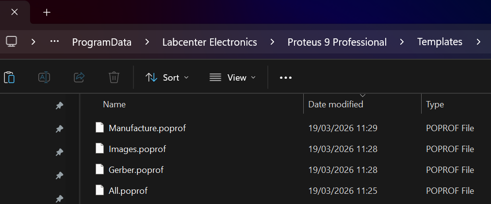
Output job profiles are stored as .poprof files in the templates directory.
Output Task Types
Each task in a profile corresponds to a specific output format. The following task types are currently available:
| Task Type | Description |
| Bitmap Image | Exports the layout as a raster image file (PNG, BMP). Configuration covers resolution, colour depth, layer selection and output mode (artwork, assembly, drill plot or testpoint plot). |
| PDF Document | Exports the layout as a PDF file with selectable layers, rotation and reflection options. |
| SVG Image | Exports the layout as a scalable vector graphic suitable for web display or documentation. |
| DXF Drawing | Exports the layout in DXF format for interchange with mechanical CAD systems. |
| Schematic PDF | Exports the schematic diagram from the Schematic Capture module as a PDF file. |
| Pick and Place | Generates a component placement file, in CSV or PKP format, for automatic insertion machines. Configuration covers column order, units and output options. See Pick and Place File. |
| Gerber | Generates the full set of manufacturing files including Gerber artwork, drill files and manufacturing notes. The Gerber task uses the same configuration as the standalone CADCAM output. See Gerber Output. |
| Bill of Materials | Generates a bill of materials from the project parts list using a selected BOM template. Output is currently available in CSV or ASCII (fixed column width) format. The configuration dialogue allows you to choose the template and output format. Additional formats such as PDF and Excel may become available in future releases. |
| 3D MCAD | Exports the board as a 3D model for mechanical CAD interchange. Supported formats are STEP (AP203 and AP214), IGES and STL. The configuration dialogue allows you to choose the export format and output options. Components that have 3D models assigned will be included in the export; those without models are flagged in the output log. |
Configuring Tasks
Tasks are added by choosing a type from the drop-down at the top of the Output Tasks list and clicking Add. Selecting a task in the list fills in the Selected task panel, where a read-only Summary describes what the task will produce with its current settings, so you can confirm a task at a glance without opening its dialogue. Rename gives the task a more meaningful name in the list, and Delete removes it from the profile.
Each task in a profile has two levels of configuration: path settings managed by the job manager and format-specific settings managed by the task's own configuration dialogue.
Path Settings
The Filestem and Sub-folder fields in the job manager control where the task's output files are written. Both fields support field codes which are resolved when the job runs. The final output path for a task is constructed as:
[Job Folder] \ [Task Sub-folder] \ [Task Filestem].[extension]
For example, with a job folder of {{DIRECTORY}}\Output, a Gerber task with sub-folder Gerber and filestem {{FILESTEM}}{{_BOARD}}, and a project called MyDesign on Board1, the Gerber files would be written to:
C:\Projects\MyDesign\Output\Gerber\MyDesign_Board1.gbr
All directories in the output path are created automatically if they do not already exist.
Format-Specific Settings
Click the Configure button to open the task's own configuration dialogue. This is the same dialogue used when running the output type standalone, so all the options familiar from individual output generation are available. The configuration is stored within the profile and is applied when the task executes as part of the job.
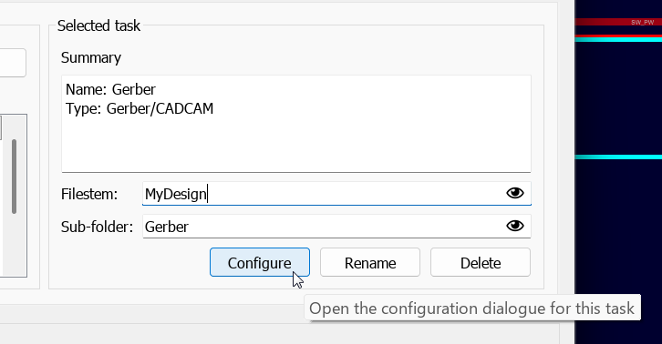
Each task has path settings and a Configure button to open its format-specific dialogue.
You do not need to set the output folder or filestem within the task's own dialogue. The job manager overrides these with its own resolved paths, ensuring that all output is directed to the correct location within the job folder structure.
Field Codes in Output Jobs
Field codes are placeholders enclosed in double braces {{}} that are replaced with project-specific values when the job executes. They can be used in the job folder path, task filestem and task sub-folder fields. The following field codes are particularly useful in output job configurations:
| Field Code | Resolves To |
| {{DIRECTORY}} | The project directory path. |
| {{FILESTEM}} | The project filename without extension. |
| {{BOARD}} | The current board name (for multi-board projects). Empty for single-board projects. |
| {{VARIANT}} | The currently selected assembly variant name. |
| {{REV}} | The revision number as set in Design Menu > Edit Design Properties in the schematic module. |
| {{TITLE}} | The project title as set in the design properties. |
| {{AUTHOR}} | The project author as set in the design properties. |
| {{DOCNO}} | The document number as set in the design properties. |
Conditional Separators
Any field code can include separator characters (underscore, hyphen or space) inside the braces, either before or after the code name. When the property resolves to a non-empty value, the separators are included in the output. When the property is empty, the entire field code, including its separators, resolves to nothing. This avoids stray separators in the filename. See Separators for the full rule.
Example:
A filestem of {{FILESTEM}}{{_BOARD}} resolves as follows:
- Single-board project: MyDesign (no trailing underscore)
- Multi-board project, board named MainBoard: MyDesign_MainBoard
The same pattern works for variants: {{FILESTEM}}{{_BOARD}}{{_VARIANT}} adds the variant name only when a variant other than the base design is selected.
The eye icon beside each field code edit box toggles between displaying the raw field code expression and the resolved text for the current project. This is useful for verifying that your field code expressions will produce the expected paths.
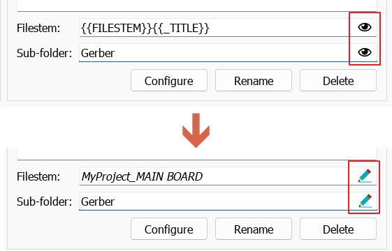
The eye icon toggles between the field code expression and the resolved path for the current project.
For the complete list of available field codes and further examples, see the Field Codes reference topic.
Layer Selection
Many output task types present a layer selector panel in their configuration dialogue. Each layer checkbox supports a tri-state selection that allows you to override the automatic layer detection.
| Icon | State | Description |
| ✱ | Auto | The layer is included or excluded automatically based on whether the design has content on that layer, and the checkbox shows which way that decision went. The label is drawn in the normal font weight. This is the default for all layers. |
| ✎ (bold) | Manual On | The layer is forced on: the checkbox is ticked and the label is drawn in bold. It will be included in the output even if the design has no content on that layer. |
| ✎ (bold) | Manual Off | The layer is forced off: the checkbox is cleared, and the label is drawn in bold. It will be excluded from the output even if the design has content on that layer. |
Read the two columns together. The pencil glyph and the bold label tell you that the layer has been set by hand rather than left to the software; the checkbox itself tells you whether that manual setting is on or off. A layer left on Auto carries the asterisk glyph and a normal weight label.
Clicking a layer checkbox cycles through the three states and then returns to Auto, so a third click always restores the automatic behaviour.
Manual overrides stored in a job profile persist across sessions and are applied automatically each time the job runs. This is the key benefit of configuring layers within an output job rather than through a standalone output dialogue, where all layers reset to Auto each time the dialogue opens.
Overrides are stored independently for each output mode (Artwork, Assembly, Drill and Manufacturing), so adjustments made in one mode do not affect the layer settings in another. For example, manually enabling a mechanical layer for artwork output does not change which layers are selected for the drill plot.
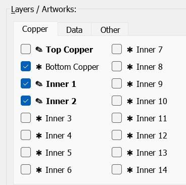
The layer selector with Auto and Manual states visible. Top Copper contains data but is excluded.
For a full description of the layer states and the Turn On, Turn Off and To Auto controls, see the Manufacturing Outputs dialogue help.
Folder Cleanup
Output is never written directly into the destination folder. Each task writes into a hidden, temporary staging folder created inside the destination, and only once every task has finished is the staged output merged into the destination, one file at a time. If the job is aborted, fails, or Proteus closes unexpectedly partway through, the destination folder is left completely untouched; only the temporary staging folder is affected, and any leftover staging folder from an interrupted run is cleaned up (or offered for manual recovery) the next time the job is generated.
A Folder Mode drop-down controls how the merge treats files that already exist in the destination but were not produced by the current run:
- Shared (the default), the folder may hold other files, such as the project itself, and nothing already there is ever removed automatically. A second drop-down, Superseded output, controls what happens to existing files that look like an earlier version of this profile's own output, judged by matching sub-folder, extension and a shared file name prefix: Ignore takes no notice of them, Report (the default) lists them in the output log, and Offer clean-up additionally asks whether to move them to the backup folder. Nothing is removed in Shared mode without this explicit confirmation.
- Dedicated, the folder is treated as this profile's own output folder. Existing files not produced by the current run are presumed stale and offered for confirmed removal, moved to the backup folder rather than deleted outright. The Clean stale files without confirming checkbox suppresses this prompt for future runs; destinations covered by a confirmation guard (see below) still prompt regardless of this setting.
In both modes, Proteus project-family files, .pdsprj, .pdsbak, .pdsclip and .poprof, are never overwritten or removed by the merge, however they came to be in the folder.
Backup
Before an existing file is overwritten or removed, it is moved into a backup folder named .ojm-backup, so nothing is ever permanently lost by a single run. Its location depends on the folder mode:
- In Dedicated mode, the backup folder is created alongside the destination, named <destination folder name>.ojm-backup, falling back to inside the destination if the parent folder is not writable, for example a drive root.
- In Shared mode, the backup folder is always created inside the destination itself, as <destination>\.ojm-backup\, so that nothing is ever written outside the folder you configured.
Only the specific files that are overwritten or removed are placed in the backup; the whole destination folder is never renamed or copied wholesale. A backed-up copy is only ever overwritten by a newer displaced copy of the same file, never deleted by the Output Job Manager.
In Dedicated mode this normally keeps the destination containing only the current run's files plus one generation of backup. If you want to retain the output of every run rather than relying on the backup, use the {{REV}} field code in the job folder path so that each revision is written to its own directory (see the worked examples below).
Confirmation Prompts
Certain destinations are always treated with extra caution, regardless of the Folder Mode and auto-clean settings. A drive root or network share root always prompts for confirmation before any overwrite. A top-level folder, the project's own folder, or an existing Output Job backup folder prompts the first time a run would overwrite or remove anything there, after which the confirmation is remembered for that profile until the destination changes.
In multi-board mode, files placed by one board are recognised as part of the same job and are never treated as stale or superseded by another board processed later in the same run. However, if a Dedicated folder is shared by all boards without a {{BOARD}} field code in the job folder path, a board's output from a previous run of the job can be offered for removal the next time the job is generated. Include {{BOARD}} in the folder path to give each board its own destination and avoid this; the Output Job Manager logs a warning when it detects this configuration.
Zone Regeneration
Copper zone fills must be fully up to date before generating manufacturing output such as Gerber files. The job manager provides an Always Regenerate Zones checkbox (enabled by default) that controls this behaviour:
- Checked (default), forces a complete regeneration of all copper zones before any output is generated or the pre-production checker is run. This guards against partial regeneration defects where some zones may not reflect the latest design changes.
- Unchecked, the job manager waits for any background zone renders to complete but does not force a full regeneration. This is faster but assumes zones are already up to date.
If zone regeneration is cancelled by the user, the job is aborted for the current board. When a full forced regeneration has been performed, the pre-production checker is told to skip its own zone regeneration step to avoid redundant work.
Multi-Board Output
For projects containing multiple boards, the Output Job Manager provides two modes of operation controlled by the Current board only and All boards radio buttons.
When Current board only is selected, the job generates output for whichever board is currently active in the layout editor. This is the default mode and is appropriate for single-board projects or when you want to generate output for one specific board.
When All boards is selected, the job iterates across every board in the project and generates the full set of output tasks for each one. Use the {{BOARD}} or {{_BOARD}} field codes in the sub-folder or filestem fields to separate the output for each board into its own directory or filename.
Example folder structure for multi-board output:
Job folder: {{DIRECTORY}}\Output
Gerber sub-folder: {{BOARD}}\Gerber
Pick and Place sub-folder: {{BOARD}}\Assembly
This produces a directory tree such as:
C:\MyProject\Output\MainBoard\Gerber\
C:\MyProject\Output\MainBoard\Assembly\
C:\MyProject\Output\PowerBoard\Gerber\
C:\MyProject\Output\PowerBoard\Assembly\
If two boards produce an output file at the same path within the same run, the job manager detects the collision and aborts the job with an error message. To avoid this, include {{BOARD}} or {{_BOARD}} in the job folder path or task filestem so that each board's output is written to a distinct location. This does not apply to the manifest and log files, which are shared by design when boards use the same destination.
In Dedicated folder mode, a board's output is only protected from clean-up while boards are sharing a destination within the same run. If a Dedicated destination is shared by all boards without a {{BOARD}} field code in the job folder path, a board's output from a previous run can be offered for removal as stale the next time the job is generated. See Folder Cleanup.
Pre-Production Checking
The Output Job Manager integrates with the pre-production checker (PPC) to verify design integrity before generating manufacturing data. The pre-production checker drop-down offers three modes:
- As needed, the checker runs only if the design has been modified since the last check.
- Always (default for new profiles), the checker runs unconditionally before every generation, regardless of whether issues have previously been flagged.
- Never, the checker is skipped entirely.
The pre-production checker runs automatically without displaying its dialogue. If the checker reports failures, a warning is logged but output generation continues; this allows you to review the PPC results in the output log alongside the generated files. A notification is shown at the end of the job if the PPC did not pass.
Setting the pre-production checker to Never is not recommended. Manufacturing data generated without a design rule check may contain unconnected nets, clearance violations or missing drill spans. These errors are far more costly to correct after board fabrication than before. Leave this set to Always unless you have a specific reason to disable it.
Running a Job
Click Generate Output to start the job. The dialogue switches to the Output Log tab and the following sequence is performed for each board (or once, in single-board mode):
- Staging and merge, output is generated into a hidden temporary folder and then merged into the job folder file by file; any existing file that would be overwritten or removed is backed up first, and depending on the Folder Mode and destination you may be prompted to confirm the merge. See Folder Cleanup.
- Zone regeneration, copper zones are regenerated or the job waits for pending renders, depending on the Always Regenerate Zones setting. See Zone Regeneration.
- Pre-production checker, runs according to the PPC mode setting (Always, As needed or Never). See Pre-Production Checking.
- Task execution, each task runs in list order. Field codes in the folder, sub-folder and filestem are resolved, output directories are created as needed and the task is executed with its stored configuration. If a task fails, the error is logged but the remaining tasks continue.
- Manifest, if the Generate Job File option is enabled, a manifest file is written listing every output file produced by each task. It is named <FILESTEM>.manifest.md (for example ControlBoard.manifest.md) so that several projects sharing one destination keep separate records, or plain manifest.md if the project has not yet been saved.
- Log file, if the Include Log option is enabled, a log file is written containing the full execution record for this board, named <FILESTEM>.output.log (for example ControlBoard.output.log) for the same reason.
To stop a running job, click Abort. The current task will complete but no further tasks will be started. Tasks that have already finished successfully are not affected.
Once the job has finished, Open Folder opens the resolved output folder in the file explorer so that you can check the result without navigating to it by hand.
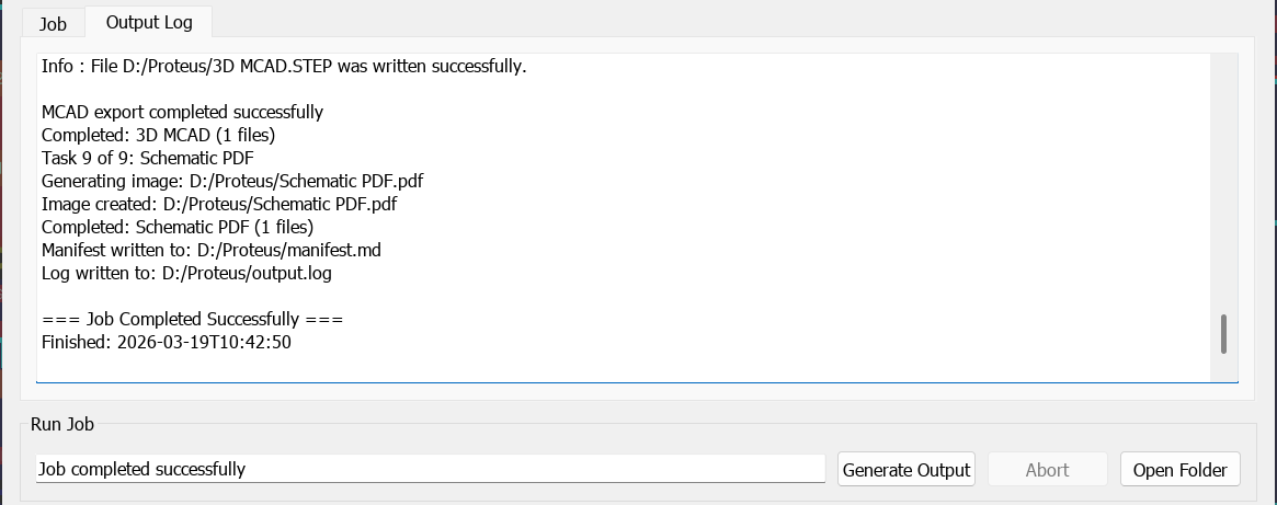
The Output Log tab shows real-time progress during job execution and a summary on completion.
Output Log
The output log provides a complete record of the job execution. A typical log shows:
- A header with the profile name and start timestamp.
- An entry for each task showing its name, progress messages and file counts.
- Pre-production checker results if the PPC was run.
- The outcome of the merge into the destination, including any stale or superseded files removed and any protected files left untouched.
- A summary footer with the completion status and finish timestamp.
The log is displayed in real time during execution and remains visible after the job completes for review. If Include Log is enabled, the same information is also written to the log file described in Running a Job, in the job folder, for archival purposes.
Worked Example: Profile Setup
The following examples walk through setting up two output job profiles for a project called ControlBoard. The first profile produces documentation deliverables (BOM and board images), whilst the second produces manufacturing data (Gerber, Pick and Place and a 3D MCAD model). Both use the {{REV}} field code to organise output by revision.
Common Setup
Open the Output Job Manager from the Output menu. Before creating profiles, set the project revision to A1 via Design Menu > Edit Design Properties in the schematic module. Ensure that the Include Log and Generate Job File checkboxes are ticked so that both a log and manifest are produced with each run.
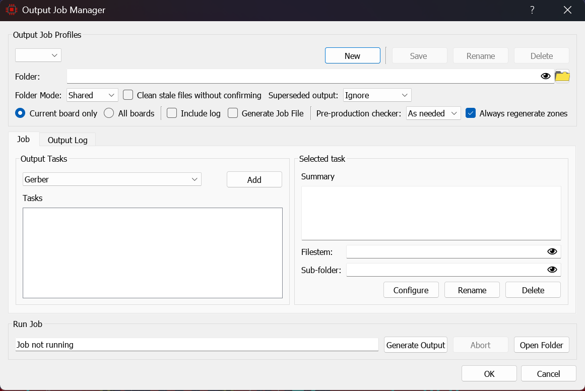
The Output Job Manager before any profiles have been created, with log options enabled.
Documentation Profile
Click New and name the profile Documentation. Set the job folder to:
{{DIRECTORY}}\Output\{{REV}}
Add the following tasks:
- Bill of Materials, set the sub-folder to BOM and the filestem to {{FILESTEM}}-BOM. Click Configure to choose the BOM template and output format (CSV or ASCII).
- PDF Image, set the sub-folder to Images and the filestem to {{FILESTEM}}-Layout. Click Configure to choose the layers to include in the PDF.
- Schematic PDF, set the sub-folder to Images and the filestem to {{FILESTEM}}-Schematic.
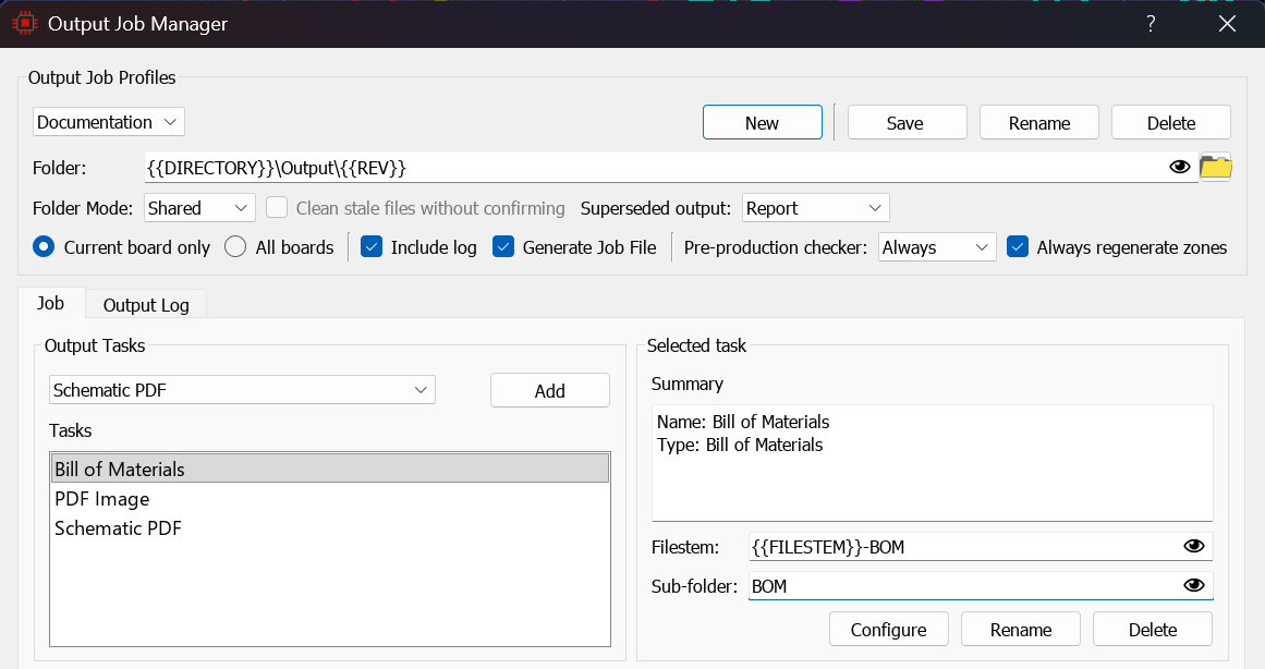
The Documentation profile with three tasks configured for BOM and image outputs.
Click Save, then Generate Output. The resulting folder structure is:
C:\Projects\ControlBoard\Output\A1\BOM\ControlBoard-BOM.csv
C:\Projects\ControlBoard\Output\A1\Images\ControlBoard-Layout.pdf
C:\Projects\ControlBoard\Output\A1\Images\ControlBoard-Schematic.pdf
C:\Projects\ControlBoard\Output\A1\ControlBoard.manifest.md
C:\Projects\ControlBoard\Output\A1\ControlBoard.output.log
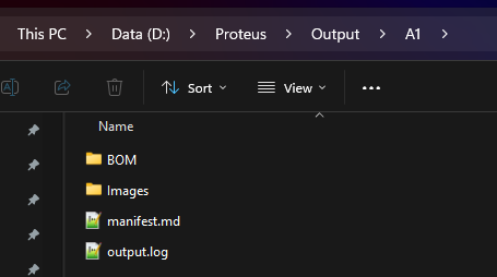
The output folder after running the Documentation profile, with sub-folders for each task type.
Manufacturing Profile
Click New and name the profile Manufacturing. Set the job folder to the same path:
{{DIRECTORY}}\Output\{{REV}}
Add the following tasks:
- Gerber, set the sub-folder to Gerber and the filestem to {{FILESTEM}}. Click Configure to open the Manufacturing Outputs dialogue. Select Gerber X2 format, verify the layer selection and set units as required by your board manufacturer.
- Pick and Place, set the sub-folder to Assembly and the filestem to {{FILESTEM}}. Click Configure to set the column order and units to match your assembly house requirements.
- 3D MCAD, set the sub-folder to Mechanical and the filestem to {{FILESTEM}}. Click Configure to select the export format (typically STEP AP214 for mechanical interchange).
Click Save, then Generate Output. The resulting folder structure is:
C:\Projects\ControlBoard\Output\A1\Gerber\ControlBoard - CADCAM *.GBR
C:\Projects\ControlBoard\Output\A1\Gerber\ControlBoard - CADCAM Drill *.GBR
C:\Projects\ControlBoard\Output\A1\Assembly\ControlBoard.csv
C:\Projects\ControlBoard\Output\A1\Mechanical\ControlBoard.STEP
C:\Projects\ControlBoard\Output\A1\ControlBoard.manifest.md
C:\Projects\ControlBoard\Output\A1\ControlBoard.output.log
Because this profile is set to Gerber X2, the drill data is written as X2 Gerber files rather than Excellon .drl files, and there is one file per drill range. Each drill filename carries the layer pair and the drill set name, so a four-layer board with blind vias produces several drill files rather than one. Selecting RS274X instead gives the single .DRL Excellon file.
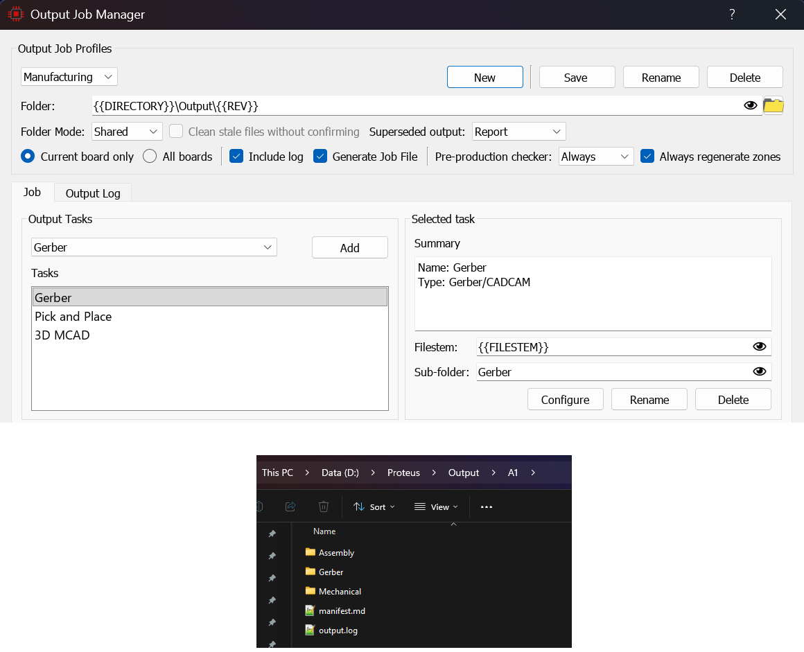
The output folder after running the Manufacturing profile, with manufacturing data organised by type.
Notice that both profiles use the same base job folder path. In the default Shared folder mode this is safe, nothing produced by one profile is removed when the other runs, but because both profiles belong to the same project they write the same ControlBoard.manifest.md and ControlBoard.output.log files, so running Manufacturing after Documentation overwrites Documentation's manifest and log (the previous copies are kept in the .ojm-backup folder, not deleted). If either profile is switched to Dedicated mode instead, the other profile's files would be presumed stale and offered for removal. Either way, if you want each profile's output and records kept fully independent, give each its own sub-path, for example {{DIRECTORY}}\Output\{{REV}}\Documentation and {{DIRECTORY}}\Output\{{REV}}\Manufacturing, to keep the two profile outputs independent.
Subsequent Revisions
The real benefit of setting up output job profiles becomes apparent when you need to generate outputs again after a design revision. Because the folder path includes the {{REV}} field code, each revision's outputs are automatically placed in a separate directory without any changes to the profile itself.
At the Next Milestone
After completing the design changes for the next revision:
- Update the revision number in the project properties (Design Menu > Edit Design Properties in the schematic module) from A1 to A2.
- Open the Output Job Manager and select the Manufacturing profile.
- Check the resolved job folder path using the eye icon. It should now show C:\Projects\ControlBoard\Output\A2\.

The Eye / Pen icon confirms the resolved path now points to the A2 revision folder.
- If any task settings need to change for this revision (for example, adding a new layer to the Gerber output), select the task and click Configure to adjust the settings. Save the profile after making changes.
- Click Generate Output.
The complete fileset is generated into the new revision folder. The previous revision's outputs in the A1 folder are untouched. Over the life of a project, this produces a clean archive of output for every revision:
C:\Projects\ControlBoard\Output\A1\...
C:\Projects\ControlBoard\Output\A2\...
C:\Projects\ControlBoard\Output\B1\...
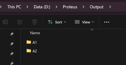
Each revision produces its own output folder, creating a clean archive over the life of the project.
Because the task configurations (Gerber format, Pick and Place column order, BOM template, 3D MCAD export format, layer selections and so on) are all stored within the profile, the entire output process is repeatable with a single click. The only change between revisions is the revision number in the project properties, which the {{REV}} field code picks up automatically.
See Also: